The Tool Editor
This page contains procedures related to the legacy editor. Try out our new editor that has a more streamlined design and provides a better app editing experience. More info.
Once you have uploaded an image containing your tool to the The CGC Image Registry using the Rabix Command Line Interface, you should provide a description of the tool's interface. The interface includes details of the tool's input and output ports, its command options, and the CPU and memory resources it requires. Providing this information writes a Common Workflow Language tool description, and allows your tool to be connected arbitrarily in workflows on the CGC.
There are two ways to enter a description of the tool's interface:
- All of the features of a tool's interface can be described using the graphical tool editor on the CGC, which you can use in the browser.
- Alternatively you can supply your own description of the tool in accordance with the Common Workflow Language. Read more on instructions on the protocol for the Common Workflow Language.
To develop and test CWL apps locally on your desktop before deploying on the CGC, use the Rabix tolkit. Develop apps locally for faster results, as you do not have to acquire an available cloud instance each time you want to test the workflow.
On this page:
Add a tool description with the tool editor
To create a new tool description using the tool editor:
- Navigate to your project.
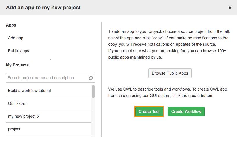
- Click the Apps tab and select +Add App.
- Click Create Tool.

Create a tool
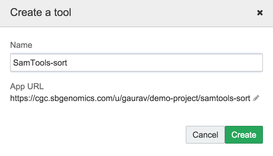
- Give your tool a name, and click the green Create button.

Name your tool
Using the tool editor
Basic principles
The tool editor is used to capture the interface of a tool, so that it can be be used in conjunction with other imported tools, and with existing workflows on the CGC.
The way the tool editor works is to build up a command that looks like the command you would enter in your terminal to run the tool, using variables in place of specific filenames or parameter values. Its use will become clearer with examples, given in the general introduction to the editor on this page, and in the extended example given in the SDK Tutorial, Worked example of uploading SamTools Sort.
Terminology
The tool editor uses the terminology of the Common Workflow Language to refer to the syntax of a command line utility. The terms map onto syntax items as follows:
| Example command syntax | cmd | [-a] | [num] | [-f] | [binary file] |
| Tool editor terminology | base command | prefix | value | prefix | value |
The base command of a command line tool is the first part of any command, before any arguments are specified. It is the utility name, together with any subcommand of the utility, in the case that the utility has multiple subcommands (for example, as a tool package will). If you need to specify a path to the utility, then the full path constitutes the base command.
The following are all examples of base commands:
grep (no subcommand)bin/my-script.shsamtools sortbwa index
The prefixes of a command line tool roughly correspond to its options, or flags, which are the single characters, such as -f or -X that follow the base command and are modified by option arguments. However, the notion of a prefix is slightly wider than the notion of an option. Specifically, if a tool requires option arguments to be passed in such a way that the option argument is not separated by a space from the option argument, but instead by some non-empty string, such as '=' then this separator is also part of the prefix.
The following are all examples of prefixes:
-f-XINPUT=
The values of the command line tool roughly correspond to its option arguments. However, there is an important difference between the two. The value can be either a literal that passed in as the option argument or an expression that resolves to the option argument. For the latter case, you may enter a JavaScript expression given in terms of features of the tool execution as a value of the tool; the value of this expression will be treated as the option argument for the prefix preceding it. Information on how to enter an expression in place of a literal is given in the documentation on dynamic expressions in tool descriptions.
The following are all examples of values:
myfile.ext9$job.allocatedResources.cpu
The tool editor layout
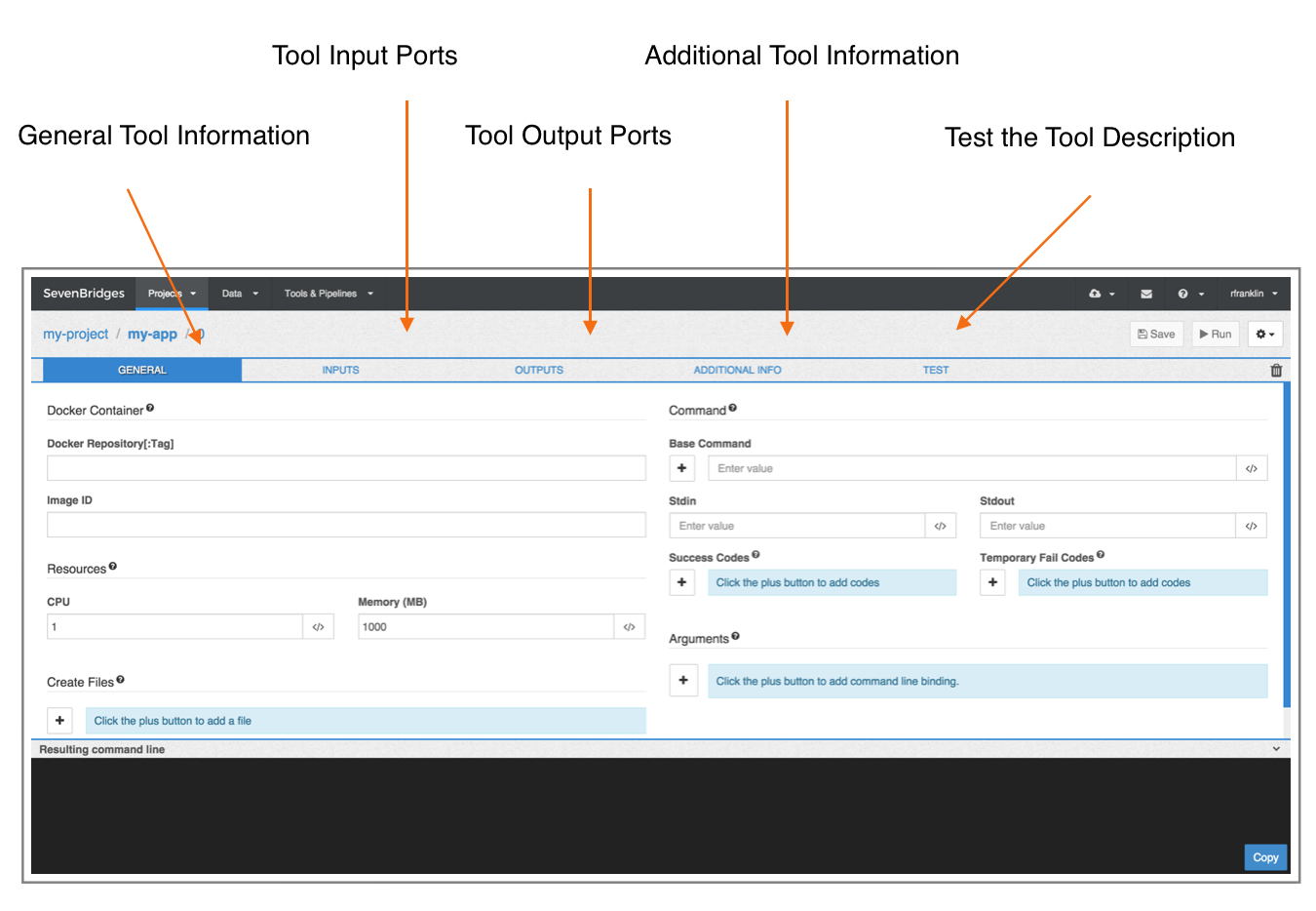
The tool editor consists of five tabs, corresponding to different parts of the tool description, some additional details used to label the tool in graphical interfaces, and a tab on which you can test the correctness of a tool description.
Information on the tabs is provided in the following five pages:
- The tool's General Information
- The tool Input ports
- The tool Output ports
- Additional Tool Information
- A Test tab

A note on tool inputs
In the tool editor, you will be prompted to describe a tool's inputs. Inputs in this sense include data, such as files, as well as parameters, such as integers, or arrays.
A note on arguments
The way that you specify the arguments of the subcommand being described depends on the argument type:
- Arguments related to inputs (files and parameter settings) are described on the Inputs tab.
- Arguments that are not related to any specific input—such as those based on resources allocated to the job—can be entered in the Arguments field on the General Information tab.
- The executable name of the subcommand, and any other part of the command that you want to fix for every execution of the tool is entered in the field Base Command on the General Information tab.
Dynamic expressions
The icon </> in a field indicates that you can enter an expression in that field; i.e., rather than giving a literal value, you can specify that the value is a function of something else. Expressions are entered in JavaScript. See the page on dynamic expressions in tool descriptions for details of hardcoded variables that are available in these expressions, and examples of their use.
Access the tool description as a JSON object
Once you have described a tool in the tool editor, you can access its Common Workflow Language description as a JSON object. If you want to familiarize yourself with writing CWL by hand, inspecting these automatically generated files can be helpful.
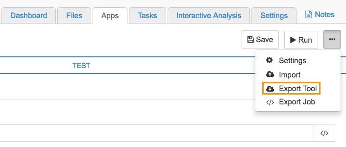
To access the CWL description of your tool from the tool editor click the ellipsis menu in the top right hand corner and select Export Tool.

Alternatively, you can use the API to download the CWL description of your tool. See the documentation on the API for details.
Updated less than a minute ago
